•Calibrate projected textures onto 3D objects using Calibration Markers.
•Calibration Markers operate on Surface level.
•The Surface assigned to a projector output is a 2D texture. VERTEX processes the spatial depth from the 3D Canvas space and applies it for warping the Surface so the projected texture matches the physical object.
•If necessary, compensate lens distortion using geometry modifiers and additional warping.
Workflow
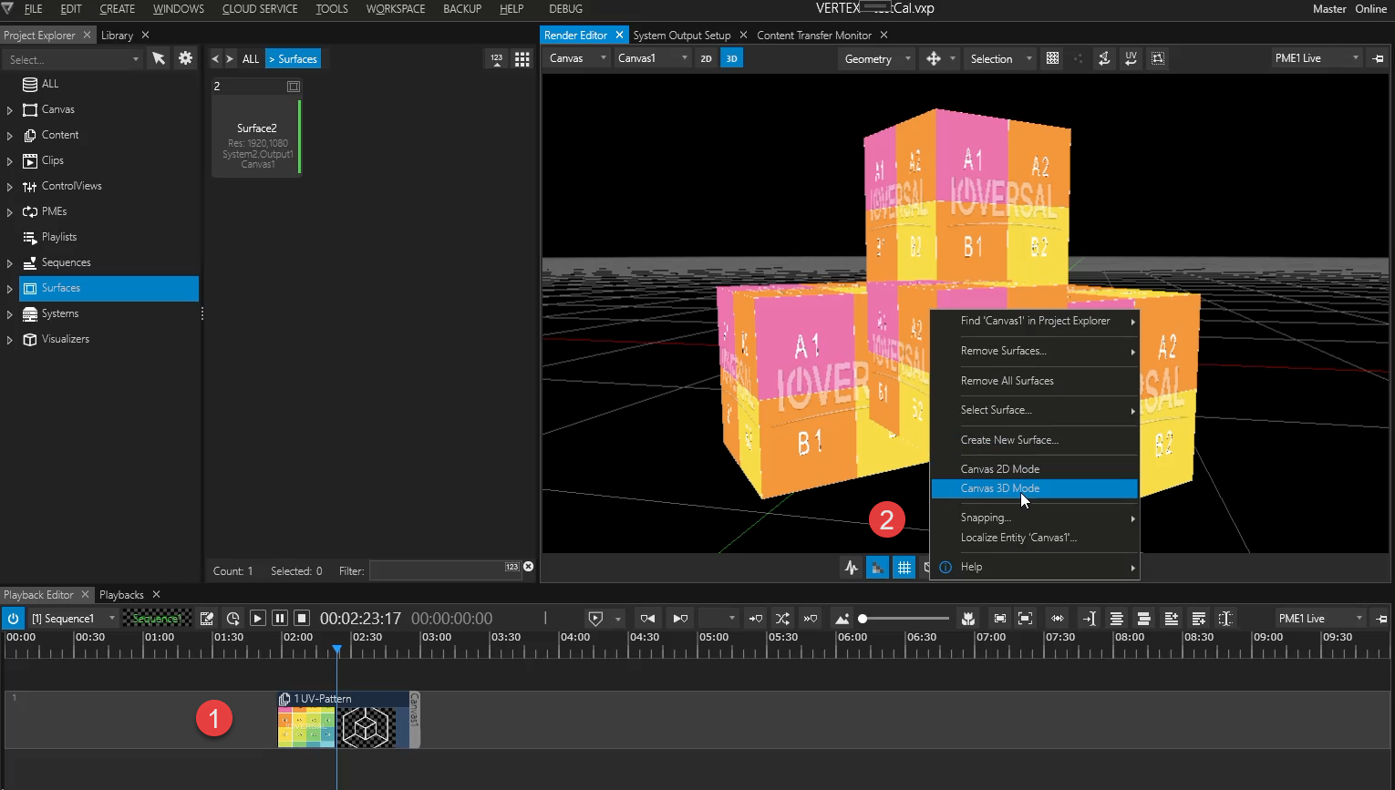
1.Add a 3D object to your project & add it to your Playback Provider - in this example we've added a UV-Pattern to the geometry as well.
2.Go to Render Editor in Canvas Mode & Switch To 3D via Render Editor context menu.
3.Disable Canvas Outline - this is optional and only serves a practical purpose for viewing larger 3D objects in the editor window.
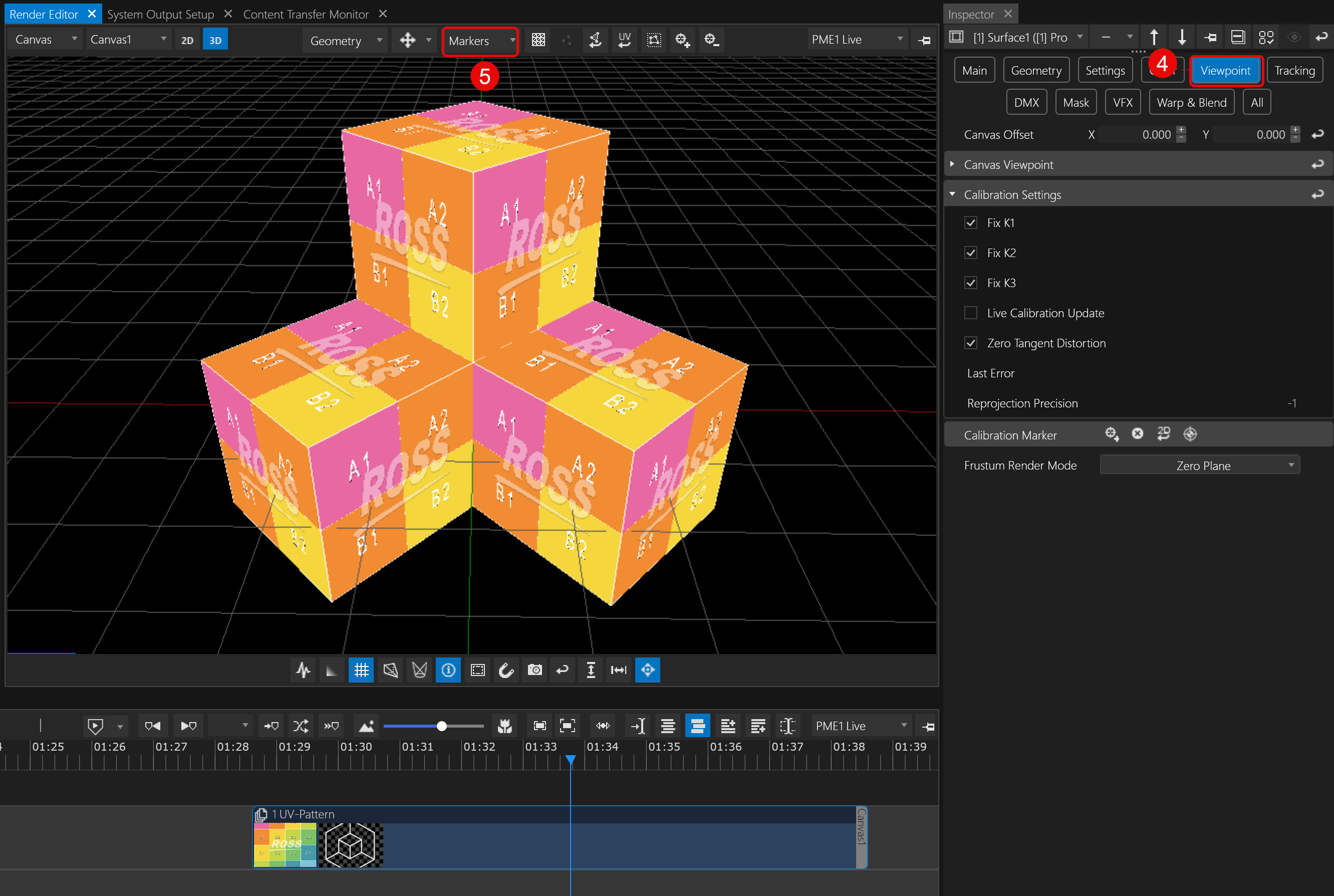
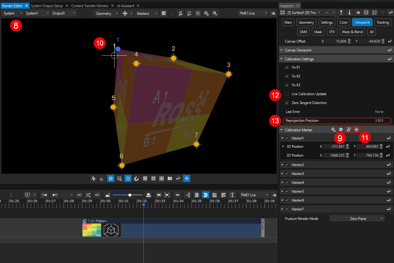
4.Inspect the Surface connected to your projector output and go to VIEWPOINT tab.
Marker Calibration requires Surface Mode set to Perspective Offset
5.In the Render Editor switch EDIT SELECTION to Markers.
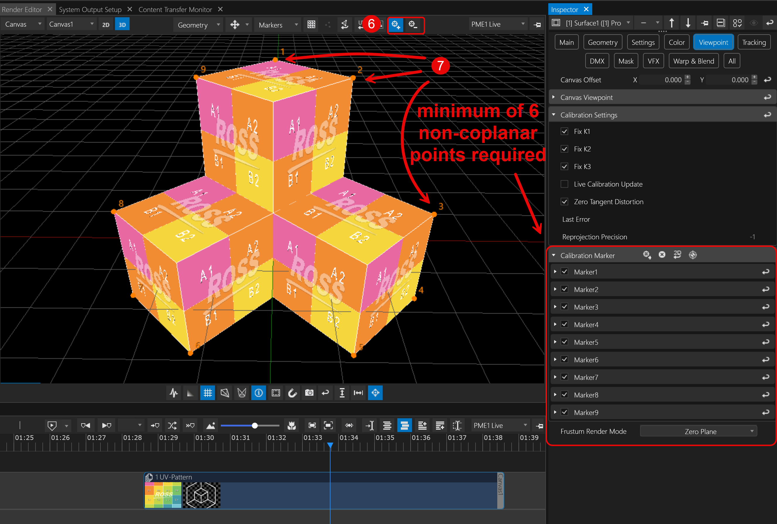
6.In the Render Editor top bar, click Add Marker to enter Calibration Marker adding mode (also, a button for a delete mode is located next to it).
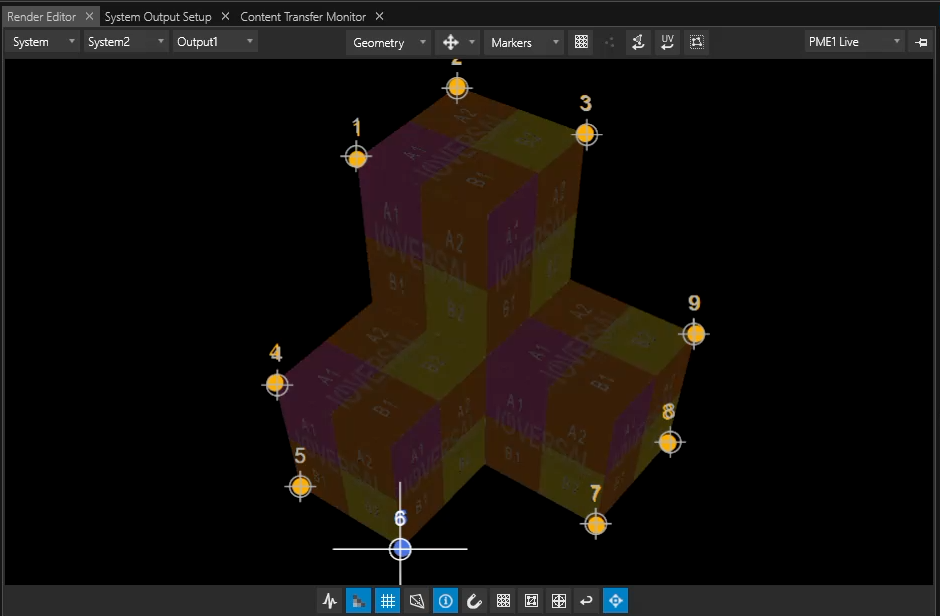
7.In the viewer, click near each corner of the 3D object — each click places a marker that snaps to the nearest mesh vertex.
Markers can also be lasso-selected and then re-positioned by CTRL-click.
A minimum of 6 non coplanar points is required, i.e. 6 markers with different levels of depth or distances.
8.Switch your Render Editor to Systems Output View.
Make sure to select the system that is physically connected to the projector when working on the Markers 2D positions. Actions on Virtual- or Backup Systems will not be visible in the output feeding the projector.
9.In the inspector, click on the 2D Reset button to prepare alignment of the Calibration Markers from both 3D and 2D space. projection space ,
10.Align Calibration Markers with the view of your projection in the real world:
a) you may click and drag the markers in the Render Editor while making sure your marker's target overlays in your projection match the corners of your physical object,
b) or toggle the selection of markers using your arrow keys first, then move the markers with SHIFT+ARROW.
Each Calibration Marker has got two sets of position values - one for 2D and one for 3D.
11.Once all markers are aligned click on Calibrate Viewpoint. VERTEX will then warp the Surface aligning the projection with the physical object.
12. Now is a good time to enable Live Calibration Update. This allows you to fine-tune the 2D/3D offset of your markers by repeating step 10. This time you'll see a live update in the warping of your Surface in the projected output.
13.You may also check the level of your accuracy with the help of Re-projection Precision property: lower value = less imperfections
 Surface Background must not be transparent as Markers would become invisible when positioned outside the model in 2D/System‘s Output View.
For better visibility of your markers, reduce the clip's opacity.
Tips for use of projectors with wide-angle lenses
Lens distortion may occur and can be compensated with with the help of Geometry Modifiers. Add an FFD from the library using VERTEX'S warping workflow.